Guide
 | The first task is to remove the rubber pad on the bottom of the case. The rubber is quite easy to tear so I used a hairdryer to heat up one corner which loosens the glue which holds it in place. I then slowly peeled it of bit by bit. Once the rubber is off you can unscrew the 5 screws which hold the whole case together. |
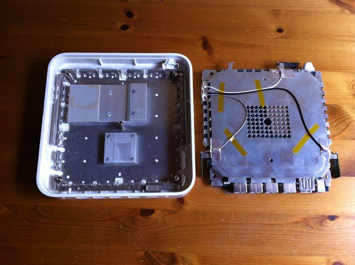 | With the screws removed, the whole circuit board and components can be removed in one piece leaving the top half of the case with an aluminium cage and heatsinks. |
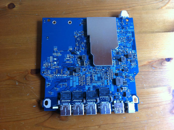 | At this point you could discard all the innards (if they are broken of course) but I decided I would reuse some of the parts so removed all the metal shielding from the circuit board. |
 | I used the rotary tool to cut right through the circuit board. |
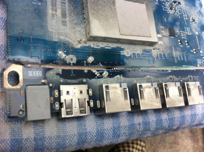
 | This gave me a mini circuit board with power, USB and 4 Ethernet ports. I then cut off the end 2 Ethernet ports to make space for the HDMI socket. Obviously with a complex board like this with traces going all over the place it’s important to check each contact on each port is still isolated. I used a multimeter for this. |
 | I also salvaged a corner of the circuit board which contains 3 LEDs (Green, blue and orange). I didn’t end up using this part as I was unsure what voltage they required and for some reason solder just wouldn’t stick. |
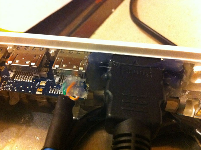
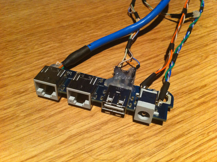 | It seems I missed a few steps along the way. To get to this stage I cut a short section of Ethernet cable with an RJ45 connecter on one end and the bare twisted pairs on the other. I then soldered 2 of the twisted pairs to the correct contacts of the Ethernet port on the circuit board. (You don’t need to solder the other 2 pairs as they’re not used). I then used the wire from the remaining part of Ethernet cable to make USB and power cables. I soldered 4 wires to the circuit board USB port and then to the 4 contacts on USB plug. For the power cable I used 3 strands for each contact. This is probably overkill, but I don’t want to risk any cables getting hot and melting. All joints were covered in heat shrink and then hot glue. This was definitely the most difficult part of the whole project as the contacts on the ports are so close together and difficult to solder by hand. |
 | This is the other end of the piece above. To the left I have soldered the power cable directly to the USB header for 5v and ground. I have also soldered a white LED to the 3.3v and ground pins. Then there is the Ethernet cable and a slimline USB plug. |
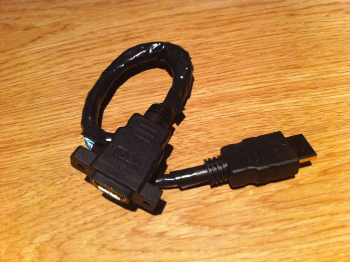 | The HDMI cable was a lot longer than advertised (40cm vs 23cm) and thus difficult to bend into the shape I needed to fit into my case. The only way to achieve this was to remove the thick rubber outer cable, bend into the correct shape and size and then insulate with electrical tape. |
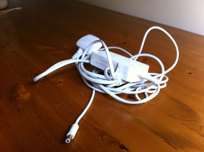 | For the power supply I cut off the white lead from the 12v Apple supply, cut off the black lead from my generic 5v supply and soldered the white lead to the 5v supply. Very straightforward, just made sure the polarity was correct using a multimeter. |
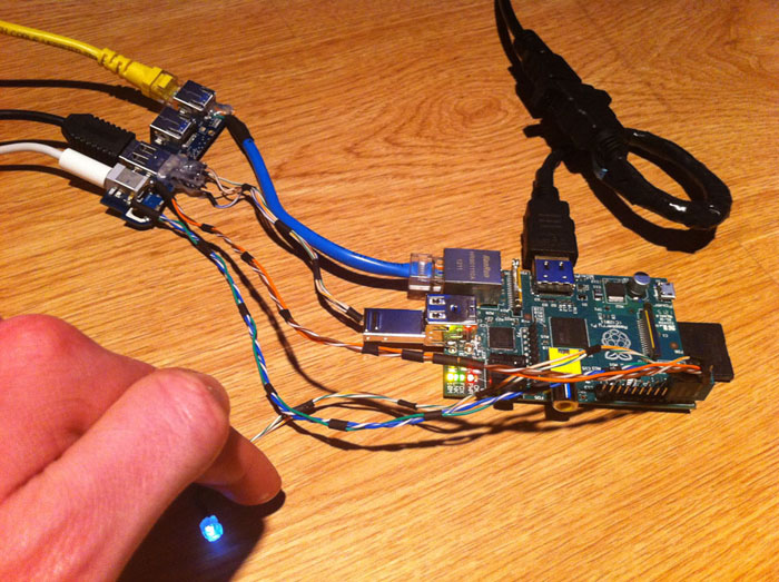 | Here I’ve plugged in the cables into the original Apple ports and then my extension cables into the Pi. The USB header plugs into the GPIO making sure it’s plugged into the correct pins!! The LED works, hooray! (It’s running on 3.3v as it was way too bright directly on the 5v pin) |
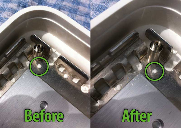 | Now the internals are done, back to the case. To remove the aluminium cage I had to remove each of the white bits which were holding it in place. I used a soldering iron to melt then scrape them off. |
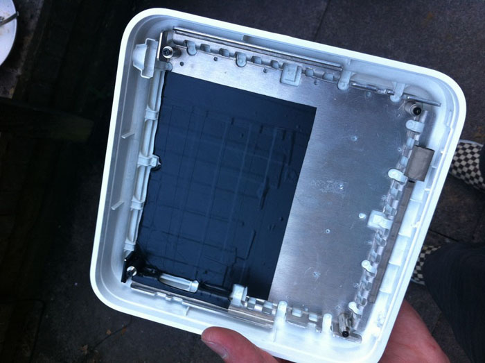
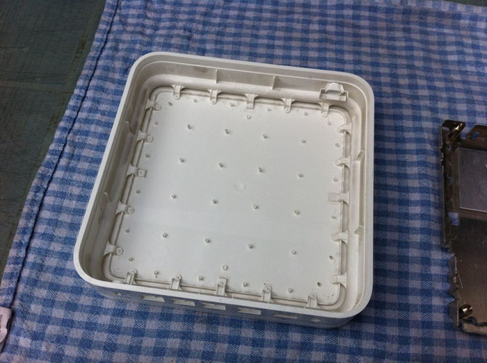 | Once that’s done you have the plastic case… |
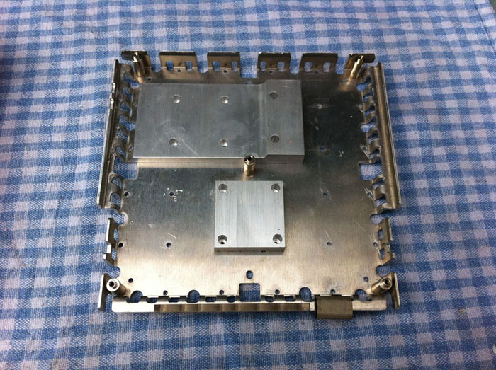 | … and the aluminium cage with heatsinks |
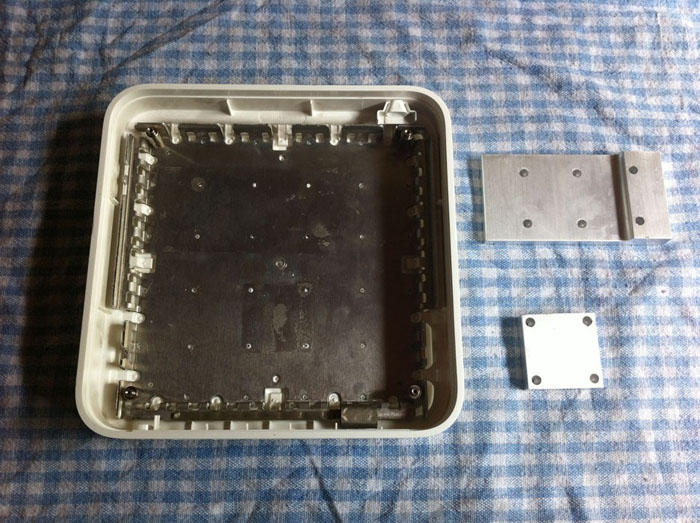 | Once the aluminium had been removed I used pliers to pull off the heatsinks which are held in place by glue and also removed the little pillar in the centre. You could just leave the aluminium in the case and pull off the heat sinks but I wasn’t sure how they were attached and didn’t want to risk damaging the case. |
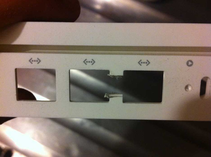 | I then used the rotary tool to merge 2 of the Ethernet port holes into 1 hole for the HDMI port. |
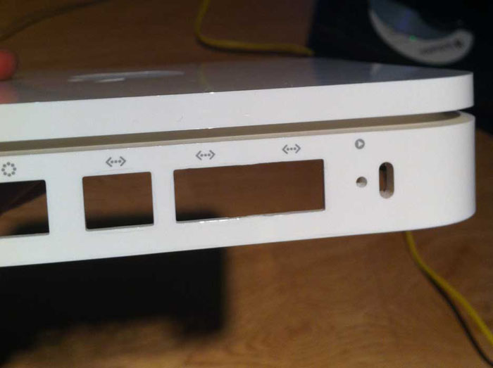 | Looks good! |
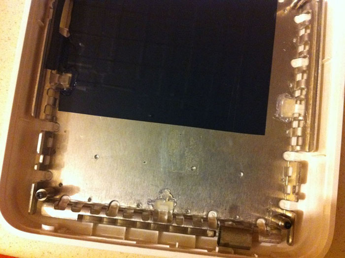
 | I then covered a section of the aluminium in several layers of electrical tape to provide some insulation for the Pi to sit on. To the left of the photo you’ll see I cut off quite a bit of aluminium upright edges to give a bit more space for the Pi and its audio and composite ports. Similarly I cut a hole and insulated the aluminium to the bottom of the photo to make space for the SD card. |
 | The aluminium cage actually clicks quite nicely into place in the white plastic case but it could potentially come apart meaning the top of the Airport Extreme could come off. So I hot glued this back in place. |
 | Next I secured the ports to the back of the case. As I used original circuit board for the power, USB and Ethernet it was already fairly secure as it sort of slots into place and held in place when you screw on the lid. But I added a bit of hot glue just to be sure! The HDMI port was fairly chunky and already fit into the gap quite well as it is, but again I applied some hot glue to ensure it wouldn’t move out of place when plugging in a cable from the outside. |
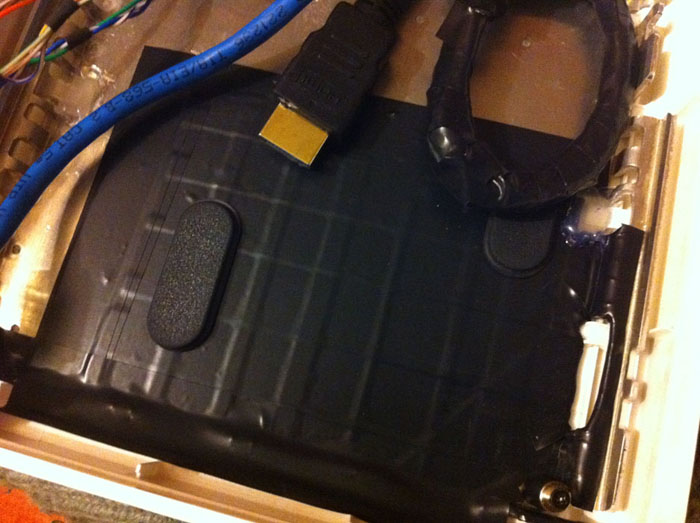 | I then glued these black rubber pads in place to lift the Pi slightly from the insulated case as an added safety measure. |
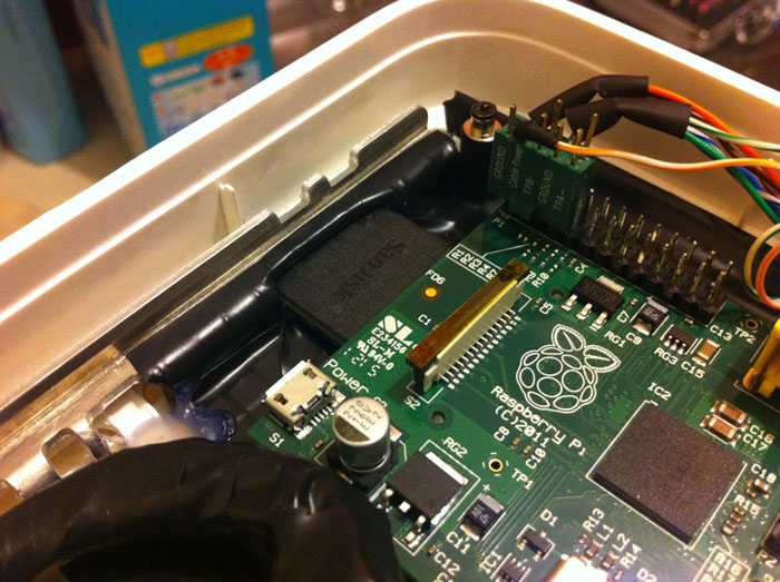 | Here’s the Pi in place with the SD card going through the hole I made. |
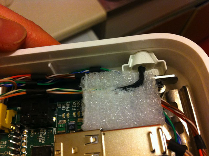 | The LED is wedged into a piece of foam which holds it at just the right height to point out of the frosted window in the case. The foam also butts up against the USB ports and the case holding everything in place. |
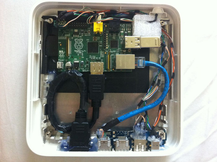 | Here’s the whole thing. The Pi is held in place by the HDMI cable at the bottom (which it quite stiff), the SD card on the left and the foam block on the right and top, plus various cables. The whole thing is quite secure like this and can be turned upside down without the Pi moving. With the lid on, which is actually the bottom of the case, it is quite a snug fit and further secures the Pi via the GPIO/USB header. |
 | I had to put some electrical tape over the LEDs on the Pi as they were so bright you could see them through the thin plastic of the case plus light leaked out of the ventilation holes (which are well hidden by Apple at the top and bottom of the case). |
 | Screw the case back together, stick the rubber pad back on, which should still have more than enough ‘stick’, and you're done! |
 is a trademark of
  is a trademark of the